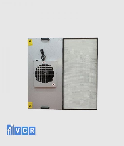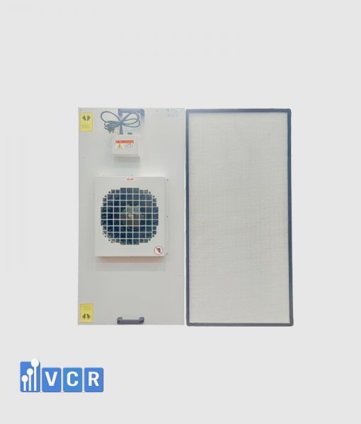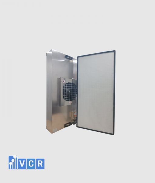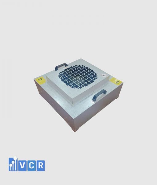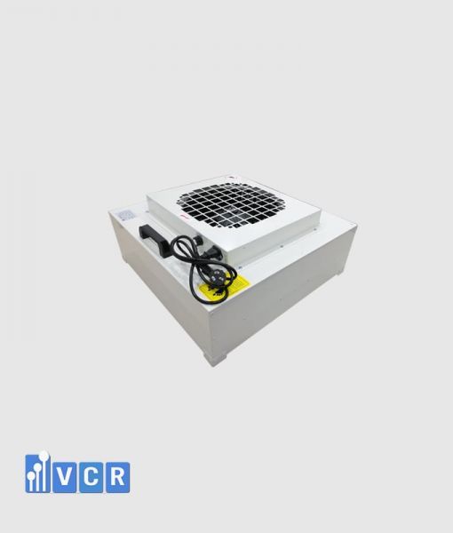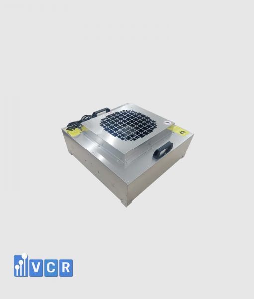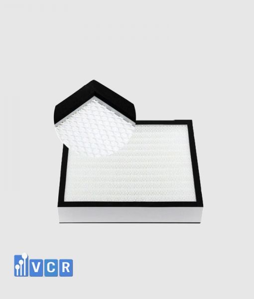


Selecting the appropriate Fan Filter Units (FFUs) is a critical consideration when developing ISO Class 5 cleanroom environments for electronics and semiconductor manufacturing. This technical case study examines how cleanroom contractors can determine FFU quantities, airflow requirements, HEPA filter classifications, and control configurations to meet project specifications while balancing cleanliness, energy efficiency, and operational reliability.
- Project Overview: ISO Class 5 Cleanroom Requirements
- The Engineering Challenge: Balancing FFU Quantity, Airflow, Filtration, and Control
- Understanding ISO Class 5 Air Cleanliness Requirements
- Preliminary Calculation of the Required Number of FFUs
- Calculating the Total FFU Airflow Requirement
- Selecting HEPA H14 Filters for ISO Class 5 Applications
- Selecting EC Motors and FFU Control Systems
- FFU Layout and Airflow Distribution in the ISO Class 5 Zone
- Technical Specifications Contractors Should Confirm Before Purchasing FFUs
- The Role of VCR Cleanroom Equipment as an FFU Supplier
- FFU Factory Testing and Site Acceptance Considerations
- Preliminary Technical Results of the Proposed FFU Configuration
- Key Engineering Lessons from the FFU Selection Process
- Frequently Asked Questions About FFUs for ISO Class 5 Cleanrooms
- Contact VCR Cleanroom Equipment for FFU Supply and Technical Consultation
Technical note: This is an illustrative engineering case study based on a hypothetical cleanroom project, not a documented project completed by VCR. All calculations and equipment specifications are provided for educational purposes and must be verified against actual project requirements.
Project Overview: ISO Class 5 Cleanroom Requirements
A cleanroom construction contractor is responsible for implementing a controlled manufacturing area within a precision electronics production facility. The manufacturing process includes operations requiring strict airborne particle control to reduce the risk of particle deposition on sensitive components.
According to the hypothetical project specifications, the critical working area must achieve ISO Class 5 cleanliness under ISO 14644-1. The contractor intends to install ceiling-mounted Fan Filter Units equipped with high-efficiency filtration to supply filtered air directly into the manufacturing environment.
The preliminary project parameters are:
-
Industry: Precision electronics and semiconductor-related manufacturing.
-
Controlled area: 12 m².
-
Clean zone dimensions: 4,000 × 3,000 mm.
-
Reference height: 3,000 mm.
-
Target cleanliness classification: ISO Class 5.
-
Proposed equipment: Fan Filter Units equipped with HEPA filtration.
-
System implementation: Cleanroom construction contractor.
-
Proposed equipment supplier: VCR Cleanroom equipment.
The 12 m² area is assumed to be a localized clean zone within a manufacturing environment supported by an appropriate background air-control system.
The contractor must establish clear boundaries for the controlled zone, define the intended operational state, and determine the relevant particle sampling locations.
The objective is not simply to install a sufficient number of FFUs. The contractor must also ensure suitable airflow distribution, minimize stagnant regions, control airborne particle migration, and establish an effective testing strategy after installation.
For semiconductor-related manufacturing, special consideration may be required for equipment-generated particles, personnel movement, process heat loads, and contamination-sensitive manufacturing operations.
The Engineering Challenge: Balancing FFU Quantity, Airflow, Filtration, and Control
The contractor faces four interconnected technical challenges: determining the appropriate number of FFUs, selecting their operating airflow rates, specifying filter efficiency, and choosing suitable motor and control configurations.
Installing too few FFUs or distributing them incorrectly may create areas where filtered airflow is insufficient. Particles generated by equipment, personnel, or surrounding activities may accumulate or migrate toward contamination-sensitive surfaces.
Conversely, installing excessive FFUs may increase capital expenditure, electrical demand, heat generation, noise, and maintenance costs without producing proportional improvements in cleanliness.
Excessively high airflow velocities can also generate undesirable turbulence around production equipment and working surfaces.
Another challenge is the relationship between fan performance and filter resistance. An FFU's airflow rating in a manufacturer’s catalogue does not necessarily represent the airflow available under actual operating conditions.
The fan must overcome resistance from the installed filter and any additional system components while maintaining the required airflow.
Consequently, FFU selection must consider the operating point on the fan performance curve, ceiling layout, contamination sources, return-air arrangement, and overall cleanroom airflow strategy.

Understanding ISO Class 5 Air Cleanliness Requirements
ISO Class 5 is an air cleanliness classification defined by airborne particle concentration under ISO 14644-1.
For particles equal to or larger than 0.5 µm, the ISO Class 5 concentration limit is 3,520 particles per cubic meter.
For particles equal to or larger than 0.3 µm, the corresponding concentration limit is approximately 10,200 particles per cubic meter.
These values describe airborne particle concentrations within the classified environment. They do not represent the filtration efficiency of an individual FFU.
An important engineering consideration is that ISO 14644-1 does not prescribe a fixed number of FFUs per square meter.
Neither the use of HEPA H14 filtration nor the selection of a particular air velocity automatically guarantees ISO Class 5 compliance.
Actual cleanliness depends on several factors:
-
Airflow distribution and contamination removal.
-
Particle generation from production equipment.
-
Personnel activity and operational procedures.
-
Room geometry and equipment arrangement.
-
Return-air pathways.
-
Filter installation integrity.
-
Background environmental conditions.
The contractor must therefore establish an appropriate airflow design and verify airborne particle concentrations after the system has been installed, adjusted, and prepared for classification testing.
Preliminary Calculation of the Required Number of FFUs
For this illustrative project, the contractor considers ceiling-mounted FFUs with nominal dimensions of 1,175 × 575 mm.
The preliminary technical parameters for each unit are:
-
FFU dimensions: 1,175 × 575 mm.
-
Nominal plan area: approximately 0.676 m².
-
Target operating airflow: 900 m³/h.
-
Filter classification: HEPA H14.
-
Motor type: EC (Electronically Commutated).
-
Control method: Adjustable fan speed.
These parameters are hypothetical. The specified airflow of 900 m³/h must be verified using the actual FFU performance characteristics at the anticipated operating pressure.
Step 1: Calculate the controlled area
The clean zone measures 4 m × 3 m.
A = 4 × 3 = 12 m².
Step 2: Evaluate a preliminary FFU arrangement
Assume that the contractor considers installing 12 FFUs in a ceiling arrangement compatible with the clean zone layout.
The combined nominal plan area of the FFUs is:
A_FFU = 12 × 1.175 × 0.575 = 8.1075 m².
The nominal ceiling coverage ratio is:
Coverage ratio = 8.1075 / 12 × 100%.
Nominal ceiling coverage ≈ 67.6%.
This percentage describes the combined equipment footprint relative to the controlled area.
It does not represent the effective filter surface area, the actual uniform airflow coverage, or proof that the environment will achieve ISO Class 5.
In a real project, the contractor must verify ceiling-grid compatibility, structural support, usable filter face area, maintenance access, and possible interference with lighting, fire protection, and monitoring devices.
Preliminary selection outcome
A configuration of 12 FFUs is retained as one possible engineering option because it provides substantial nominal ceiling coverage.
However, the final quantity must be confirmed through airflow calculations, equipment layout studies, contamination risk assessment, and appropriate testing.
Twelve FFUs should not be interpreted as a standard requirement for every 12 m² ISO Class 5 clean zone.
Calculating the Total FFU Airflow Requirement
After establishing a preliminary equipment arrangement, the contractor must evaluate the total airflow and verify the operating capacity of individual FFUs.
The basic airflow equation is:
Q_total = N × Q_FFU
Where:
-
Q_total = Total airflow supplied by the FFUs, m³/h.
-
N = Number of installed FFUs.
-
Q_FFU = Airflow per FFU at the specified operating point, m³/h.
For the hypothetical arrangement:
Q_total = 12 × 900.
Total target airflow = 10,800 m³/h.
If a reference height of 3 m is used, the corresponding geometric volume is:
V = 12 × 3 = 36 m³.
The ratio between the total airflow and the reference volume is:
ACH = 10,800 / 36.
Illustrative air-change ratio = 300 h⁻¹.
ACH stands for Air Changes per Hour and represents the ratio of volumetric airflow to the selected room volume.
In this example, the calculated value is intended only as an engineering reference.
For localized clean zones and unidirectional airflow applications, ACH alone does not adequately describe contamination removal performance or demonstrate ISO Class 5 compliance.
Actual cleanliness depends on airflow organization, contamination generation, and operating conditions.
It is also essential to distinguish the FFU's maximum advertised airflow from its actual delivered airflow.
A unit rated at 900 m³/h under specific laboratory conditions may deliver less airflow after accounting for filter pressure drop and installation conditions.
The contractor should therefore request fan performance curves or verified airflow data at the required operating point.

Selecting HEPA H14 Filters for ISO Class 5 Applications
The hypothetical project specifies HEPA H14 filtration for the proposed Fan Filter Units.
Under the EN 1822 classification framework, an H14 HEPA filter has a minimum overall efficiency of 99.995% at the Most Penetrating Particle Size (MPPS).
MPPS refers to the particle size at which the filter exhibits its lowest collection efficiency under the specified testing conditions.
Selecting HEPA H14 filtration provides high-efficiency particle removal at the clean-air supply point.
However, H14 filtration alone does not guarantee that the entire cleanroom will achieve ISO Class 5.
A system using high-efficiency filters may still experience unacceptable particle concentrations if airflow distribution is inadequate, filter installation leakage occurs, or particle generation exceeds removal capacity.
For procurement purposes, the contractor should evaluate:
-
HEPA filter classification and applicable testing standard.
-
Filter certificate or individual test documentation.
-
Initial pressure drop at the specified airflow.
-
Expected pressure-drop increase during operation.
-
Gasket or gel-seal configuration where applicable.
-
Accessibility for installed-filter leakage testing.
-
Filter replacement procedures and maintenance requirements.
Certain semiconductor processes may require ULPA filtration because of more stringent particle-control objectives.
However, the choice between HEPA and ULPA must be based on process requirements and technical specifications rather than the industry name alone.
Selecting EC Motors and FFU Control Systems
Motor configuration is another important factor influencing FFU performance, operating cost, and control flexibility.
For the illustrative project, the contractor considers FFUs equipped with EC motors.
EC motors use electronic commutation and commonly provide adjustable speed operation.
Compared with certain traditional AC motor configurations, EC motors may offer better electrical efficiency and more flexible control.
However, energy savings must be demonstrated using comparable airflow and operating pressure conditions.
A motor type alone is insufficient to establish the actual energy performance of an FFU.
For a system containing 12 FFUs, the contractor may consider individual control, group control, or a centralized supervisory arrangement.
Potential functions include:
-
Fan start and stop commands.
-
Adjustable fan speed.
-
Motor operation monitoring.
-
Equipment fault indication.
-
RS485 or Modbus communication where supported.
-
Integration with a Building Management System (BMS), subject to system compatibility.
If centralized control is required, the contractor should verify communication protocols, controller capacity, wiring arrangements, and available monitoring functions.
Not all EC motor FFUs support BMS connectivity as a standard feature.
The required control functions should therefore be specified before procurement.
FFU Layout and Airflow Distribution in the ISO Class 5 Zone
FFU quantity and total airflow are only part of the overall engineering solution.
The location of each unit and the movement of air through the controlled area strongly influence particle transport and removal.
In the hypothetical project, the FFUs are intended to be installed above the critical working area to provide downward filtered airflow.
The air then moves toward designated return-air locations according to the contractor's overall ventilation design.
The proposed arrangement should minimize disturbances caused by equipment, structural elements, and personnel movement.
For example, large production machines installed directly beneath the FFUs may alter the downward airflow and generate localized recirculation zones.
These disturbances can increase the risk of particle accumulation or transport toward sensitive surfaces.
The contractor must consider the following:
-
FFU arrangement above critical processes.
-
Air velocity distribution.
-
Return-air locations.
-
Obstructions and production equipment geometry.
-
Personnel movement.
-
Process-related particle sources.
-
Thermal effects from machinery.
Where appropriate, airflow visualization or Computational Fluid Dynamics (CFD) modeling may support the engineering assessment.
CFD models can help identify potential airflow disturbances, but simulation results must not be treated as proof of cleanroom compliance.
Actual performance must be verified after installation through appropriate airflow and particle concentration testing.

Technical Specifications Contractors Should Confirm Before Purchasing FFUs
Before issuing a purchase order, the cleanroom contractor should establish a complete FFU technical specification.
The specification should identify both the required equipment characteristics and the intended operating conditions.
For the ISO Class 5 project, the key technical parameters include:
-
Overall FFU dimensions.
-
Required airflow at the operating point.
-
Available external static pressure.
-
HEPA or ULPA filter classification.
-
Filter pressure drop.
-
Motor type and electrical supply.
-
Power consumption.
-
Noise level.
-
Fan speed control method.
-
Communication and monitoring requirements.
-
Housing material.
-
Sealing arrangement.
-
Installation configuration.
-
Filter replacement accessibility.
One of the most important considerations is the relationship between airflow and static pressure.
The selected FFU must provide the required airflow while overcoming the resistance associated with the installed filter and relevant system components.
The contractor should also verify compatibility with the ceiling structure and ensure that future filter replacement can be performed safely and efficiently.
Confirming these requirements before procurement reduces the risk of unsuitable equipment, design modifications, and project delays.
The Role of VCR Cleanroom Equipment as an FFU Supplier
In this illustrative case study, VCR Cleanroom equipment is positioned as an equipment supplier serving cleanroom construction contractors in Vietnam.
VCR's role is to supply Fan Filter Units and related cleanroom equipment according to contractor specifications.
VCR is not presented as the contractor responsible for overall HVAC system design, cleanroom construction, installation, or final cleanroom classification.
Based on technical requirements submitted by contractors, VCR can support equipment selection and provide relevant product information.
Typical support activities include:
-
FFU model selection according to project requirements.
-
Comparison of available equipment configurations.
-
Confirmation of dimensions and airflow specifications.
-
HEPA or ULPA filter selection.
-
AC or EC motor configuration.
-
Control-system options.
-
Product catalogues and technical documentation.
-
Commercial quotations and delivery arrangements.
-
Warranty and after-sales support according to contract terms.
For projects with specific technical requirements, contractors may submit engineering drawings, equipment schedules, or User Requirement Specifications (URS).
VCR can use these documents to coordinate product clarification and confirm available configurations with the equipment manufacturer.
A clear division of responsibilities between the equipment supplier and construction contractor supports accurate procurement and effective project coordination.
FFU Factory Testing and Site Acceptance Considerations
Equipment inspection and testing provide important evidence that supplied FFUs meet the agreed technical requirements.
Before delivery, the contractor may request manufacturer documentation, including technical catalogues, drawings, motor specifications, filter certificates, and relevant factory test reports.
Where Factory Acceptance Testing (FAT) is required, the test scope and acceptance criteria should be defined in advance.
Potential FFU test parameters include:
-
Airflow rate.
-
Electrical power consumption.
-
Operating pressure.
-
Noise level.
-
Fan speed adjustment.
-
Control functions.
-
Equipment condition and identification.
Following installation by the cleanroom contractor, site testing may include airflow measurement, installed-filter leakage testing, airflow visualization, and verification of control-system operation.
Additional cleanroom testing may include airborne particle concentration measurements according to ISO 14644-1.
ISO 14644-3 provides methods for selected cleanroom performance tests, including airflow and installed-filter leakage testing.
IEST-RP-CC036.1 provides recommended practices for evaluating FFU performance characteristics.
Importantly, testing an individual FFU does not establish the cleanliness classification of the completed cleanroom.
ISO Class 5 compliance must be demonstrated through appropriate testing of the controlled environment under the specified classification conditions.
Preliminary Technical Results of the Proposed FFU Configuration
The preliminary selection parameters are summarized below.
|
Parameter |
Illustrative Value |
|
Controlled area |
12 m² |
|
Reference height |
3 m |
|
Target cleanliness |
ISO Class 5 |
|
Proposed FFU quantity |
12 units |
|
FFU dimensions |
1,175 × 575 mm |
|
Target airflow per FFU |
900 m³/h |
|
Total target airflow |
10,800 m³/h |
|
Proposed filter |
HEPA H14 |
|
Proposed motor |
EC |
|
Control configuration |
Adjustable speed, optional group control |
|
Nominal ceiling coverage |
Approximately 67.6% |
The calculations establish an initial technical option for further evaluation.
They do not demonstrate that the proposed system is optimal or that ISO Class 5 has been achieved.
Before confirming the configuration, the contractor must verify actual FFU performance curves, operating pressure, effective filtration area, ceiling compatibility, and return-air arrangement.
The contractor must also evaluate particle generation and airflow disturbances associated with the manufacturing process.
Where analysis identifies insufficient airflow distribution or unacceptable contamination risks, the FFU quantity, arrangement, or system design may require modification.
The outcome of this case study is a preliminary engineering selection, not a documented cleanroom qualification result.

Key Engineering Lessons from the FFU Selection Process
The case study highlights several important considerations for cleanroom contractors.
First, FFU quantity should not be determined solely from floor area. The required cleanliness classification, process characteristics, particle generation, and airflow strategy must be considered together.
Second, equipment arrangement is as important as airflow capacity. Increasing the number of FFUs does not automatically improve cleanliness if airflow disturbances or poorly designed return-air paths remain.
Third, HEPA H14 filtration provides high-efficiency particle removal but cannot independently establish cleanroom performance.
Filter installation integrity, pressure drop, airflow distribution, and contamination sources all influence the resulting particle concentrations.
Fourth, the actual operating point of the FFU must be verified. Catalogue airflow values should not be interpreted without considering the pressure conditions under which they were obtained.
Finally, clear communication between the cleanroom contractor and equipment supplier helps ensure that the FFUs delivered are compatible with project specifications.
These principles are particularly important in electronics and semiconductor facilities, where production processes may be highly sensitive to airborne contamination.
Frequently Asked Questions About FFUs for ISO Class 5 Cleanrooms
How many FFUs are required for an ISO Class 5 cleanroom?
There is no universally fixed number of FFUs required for ISO Class 5 cleanrooms. The quantity depends on the controlled area, ceiling coverage, airflow capacity, contamination sources, return-air configuration, and operational requirements. Contractors must assess the complete airflow design and verify the resulting particle concentrations through appropriate cleanroom classification testing.
Can an FFU with an H14 HEPA filter guarantee ISO Class 5?
No. HEPA H14 filtration provides high particle removal efficiency, but it does not guarantee that an entire cleanroom will achieve ISO Class 5. Cleanroom performance also depends on airflow distribution, filter installation integrity, contamination generation, operating conditions, and room configuration. Compliance must be verified through airborne particle concentration testing according to ISO 14644-1.
Should contractors select AC or EC motor FFUs?
Both AC and EC motor FFUs may be suitable when they meet the project requirements. EC motors are often considered for adjustable speed operation, centralized monitoring, and potential energy efficiency improvements. However, energy performance should be compared under equivalent airflow and operating pressure conditions rather than assumed from motor technology alone.
What cleanroom area can a 900 m³/h FFU cover?
A specific cleanroom area cannot be determined from a 900 m³/h airflow rating alone. Coverage depends on the effective filter face area, air velocity, FFU arrangement, airflow pattern, contamination sources, and cleanliness requirements. The advertised airflow must also be verified at the actual operating pressure of the selected equipment.
Is ULPA filtration mandatory for ISO Class 5 cleanrooms?
No. ISO Class 5 does not universally require ULPA filtration. HEPA or ULPA selection depends on the manufacturing process, required particle control, filter performance, and overall cleanroom design. HEPA H14 may be suitable for many applications, but the complete system must be evaluated against the project requirements.
What information should contractors provide when requesting an FFU quotation?
Contractors should provide the proposed FFU dimensions, quantity, required airflow, operating pressure, HEPA or ULPA filter classification, motor type, electrical specifications, control requirements, and installation conditions. Engineering drawings or a User Requirement Specification (URS) can help the equipment supplier identify appropriate models and confirm technical compatibility.
Contact VCR Cleanroom Equipment for FFU Supply and Technical Consultation
Selecting suitable Fan Filter Units is an important part of cleanroom projects in electronics, semiconductor, pharmaceutical, medical-device, and other precision manufacturing industries.
For ISO Class 5 applications, FFU quantities, airflow requirements, filter classifications, and control configurations must be established according to engineering specifications and actual operating conditions.
VCR Cleanroom equipment supplies FFUs and related cleanroom equipment to cleanroom construction contractors in Vietnam.
VCR supports contractors with equipment selection based on submitted technical specifications, product information, catalogues, quotations, delivery arrangements, and contractual after-sales services.
VCR Cleanroom equipment – Fan Filter Unit Supplier for Cleanroom Construction Contractors
Hotline: 090.123.9008
Website: https://vietnamcleanroom.com
FFU Product Website: https://ffu.com.vn
Products: HEPA FFUs, ULPA FFUs, AC Motor FFUs, EC Motor FFUs, Centrally Controlled FFUs, and Customized FFU Configurations.
Services: Product selection support, technical documentation, equipment supply, quotations, warranty, and after-sales support.